RAG128
REMOTE ACCES 12-Bit Analog/Digital I/O Pod
Features
- Remote intelligent analog and digital I/O unit with opto-isolated RS-485 serial interface to host computer
- Eight-channel programmable gain, Successive approximation A/D converter with 12-bit resolution
- Can be used with AIM-16 multiplexer to support up to 128 differential or single ended inputs
- Eight digital I/O lines, bit-programmable as inputs or outputs
- 8031 microcontroller with 8 x 32K RAM and 8 x 32K EEPROM
- Maximum internal storage capacity of 10000 data samples for use in stand alone mode
- On-board crystal clock and three 16-bit counter/timers
- Watchdog circuit for reset on power-up and microprocessor failure
- All programming in software, No switches to set. Jumpers (3) to by-pass opto-isolators if desired.
- Designed, made, supported, and manufactured in the USA

The unit's address is programmable from 00 to FF hex and whatever address is assigned is stored in EEPROM and used as the default address at the next power-on. Similarly, baud rate is programmable for 1200, 2400, 4800, 9600, 14400, 19200, and 28800. The programmed baud rate is stored in EEPROM and used as default at the next power-on. A type 8031 microcontroller (with 32K x 8 bits RAM and 32K x 8 bits EEPROM and a watchdog timer circuit) gives RAG128 the capability and versatility expected from a modern distributed control system. RAG128 contains lowpower CMOS circuitry, an opto-isolated receiver/transmitter, and power conditioners for local and external isolated power. It can communicate at baud rates up to 28.8K baud and distances up to 4000 feet with low-attenuation twisted pair cabling.
ANALOG INPUTS
RAG128 accepts up to eight single-ended analog inputs. Input voltage ranges of ±10V, ±5V, 0-10V, and 0-5V are programmable on a channel-by-channel basis. All inputs are overvoltage protected up to 16.5V. The digitizer used is a 12-bit, successive approximation analog-to-digital converter capable of 10,000 conversions per second. Conversions may be initiated in one of three ways:a. By software
command.
b. By an on-board programmable timer.
c. By an external trigger.
The RAG128 can be used alone or it may be used with signal conditioners and analog sub-multiplexers AIM-16 and LVDT-8 or with simultaneous sample and hold amplifiers models SSH-04 and SSH-08.
ANALOG INPUT EXPANSION
RAG128 can be used in conjunction with the model AIM-16 analog input multiplexer and signal conditioner for any and all of the following applications:• More
than eight analog inputs.
• Differential inputs rather than single- ended.
• Different full-scale voltage ranges.
• Inputs from thermocouples and other low-level voltage sources.
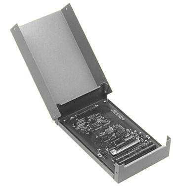
Each AIM-16 can accommodate up to 16 single-ended or differential analog inputs and contains a programmable-gain instrumentation amplifier. Amplifier gain is programmed through the RAG128. In the case of thermocouple inputs, reference junction compensation and linearization will be done as part of the host computer's application program and software routines are suppled by ACCES. For applications where watertight and/or dust-tight protection is needed, we can supply RAG128 in a NEMA 4 enclosure. Or, if 16 or 32 analog inputs are to be handled, RAG128 can be included in a RIDACS configuration and installed in a gasketed, 14-gauge steel box with stainless steel clamps on three sides of the cover and continuous heavy-gauge hinge.
DIGITAL I/O
Eight bits of digital I/O are provided for general purpose use. These can be software configured on a bit-by-bit basis for input or output. Each output can comply with user-supplied voltages up to 50 volts. The maximum current per output bit is 350mA and inductive suppression diodes are included in each circuit. There are an additional eight bits that are dedicated for use as outputs. These can be used for either channel address and gain control signals to the AIM16 or for general-purpose outputs. Note, however, that output loads are limited to 10 LSTTL loads each.COUNTER/TIMERS
Three 16-bit Counter/Timers are included on RAG128. Counter/Timer 0 is enabled by a digital input and may be clocked by either the output of Counter/Timer 1 or by an external source of up to 10 MHz. This Counter/Timer is not committed on the card and its clock, gate, and output lines are available at a 37-pin I/O connector and at screw terminals on the card. Counter/Timers 1 and 2 are concatenated to form a 32-bit pacer clock for timed A/D starts. Counter/Timer 1 may be enabled by a digital input and is clocked by an on-board, crystal-controlled 10 MHz oscillator. The output of Counter/Timer 1 provides the clock for Counter/Timer 2 and is also available at the 37-pin I/O connector and at a screw terminal on the card. The output of Counter/Timer 2 is connected to T0 of the microprocessor which could be used to initiate timed A/D starts.WATCHDOG TIMER
The built-in watchdog timer resets RAG128's microcontroller if, for some unexpected reason the microcontroller "hangs up" or if the local power supply drops below 7.25 VDC.POWER
RAG128 contains CMOS low power circuitry, an optically isolated receiver/transmitter, and voltage regulators for local power and external isolated power. The isolated section of the unit accepts 7.5 to 35 VDC and only uses about 40 milliamperes (7 mA at 12 VDC). This power could be provided by the computer's +12 VDC supply. Voltage drop in the cable will be insignificant, even if the cable is very long because so little current is drawn. Power for the rest of the unit's circuits can be provided by a separate, local power supply. Only 7.5 VDC is needed but, because onboard voltage regulators are provided, the local power can be as high as 18 VDC.
Drivers and Downloads
Full list of available Downloads: Software Packages, Drivers, Manuals, and other documents
Custom Software
ACCES also offers Custom Software Services for our products. Our prices are unbelievably low, often as inexpensive as free! If you need something tweaked to support your needs, or an entire enterprise application developed from scratch, it is definitely worth your time to inquire with us, first.
Further information about available ACCES Software:
- Redistributing Windows Drivers
- A list of ACCES drivers and the files that compose them under different versions of Windows, so you can easily redistribute ACCES cards and drivers.
Specifications
Regulatory ComplianceAnalog Inputs
- Channels: Eight, single-ended.
- Resolution: 12 binary bits.
- Accuracy: 0.02% ±l LSB.
- Input Voltage Modes: ±5V, ±l0V, 0-10V, 0-5V.
- Coding: True binary for unipolar inputs and offset binary for bipolar inputs.
- Throughput: 10K samples per second.
- A/D Type: Successive Approximation.
- Monotonicity: Guaranteed over operating temperature range.
- Gain Drift: ±5 PPM/°C.
- Trigger Source: Software command, on-board programmable timer, or external source.
Digital Inputs
- Logic High: 2.0 to 5.0 VDC at 20 µA max.
- Logic Low: -0.5 to 0.8 VDC at -0.4 mA max.
Digital Outputs
- Logic-Low Output Current: 350 mA maximum. Inductive-suppression diode included in each circuit.
- High-Level Output Voltage: Open collector, compliance with up to 50V user-supplied voltage. If no user-supplied voltage exists, outputs are pulled up to +5VDC via 10 kilohm resistors.
Programmable Timer
- Type: 82C54-2 programmable interval timer.
- Counters: Three 16-bit down counters, two permanently concatenated, with 10 MHz clock as programmable timer. One counter is uncommitted.
- Output Drive: 2.2 mA at 0.45V (5 LSTTL loads).
- Input Gate: TTL/CMOS compatible.
- Clock Input Frequency: DC to 10 MHz.
- Active Count Edge: Negative edge.
- Minimum Clock Pulse Width: 30 nS high/50 nS low.
- Timer Range: 2.5 MHz to < 1 pulse per hour
Environmental
- Operating Temperature Range: 0° to 65°C. (Optional -40°C to +80°C.)
(For Temperature De-rating considerations, refer to the "Temperature De-rating" discussion in the REMOTE ACCES Overview page that presents "Specifications common to all REMOTE ACCES pods.")- Storage Temperature Range: -50°C to +120°C.
- Humidity: 5% to 95% RH, non-condensing. Enclosure is designed to meet NEMA 4 requirements.
Power Required
- Power for the opto-isolated section can be applied from the computer's +12 VDC power supply via the serial communications cable, if a four-wire cable is used, or by a local isolated power supply. Power for the rest of the pod can be provided by a local power supply.
- Opto-Isolated Section: 7.5 to 25 VDC @ 40 mA maximum (7 mA at 12 VDC .)
- Local Power: 7.5 to 16 VDC at 150 mA
| Model | Price (USD) |
|---|---|
| RAG128 | 395.00 |
| U-RAG128 | call |
| WM-RAG128 | call |
| E-RAG128 | call |
| S-RAG128 | call |